UT23 Steering System
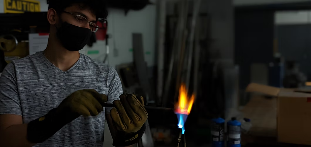
As the Steering Systems Lead of the University of Toronto's Formula Racing team, it was my task to lead a team of six to design the new steering system for UT23 which featured a fully autonomous steering system.
This was the first time the team had looked towards driverless, and it was my responsibility to bring that idea to fruition. This involved not only designing the system but also manufacturing it in the university's machine shop.
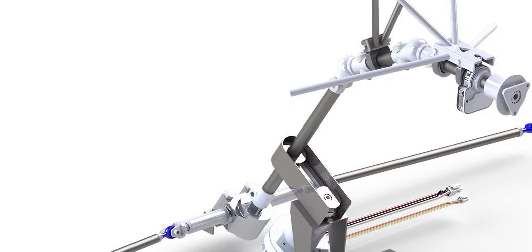
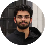
Autonomous Steering System
In order to create the closed-loop feedback system needed for autonomous control, a brushless DC motor was used alongside a rotary angle sensor. This setup allowed the control system to monitor the position of the steering as well as send accurate information to the motor.
The biggest challenge when designing the system was weighing the tight space constraints with the torque requirements of the system. In addition, the entire system had to be back-drivable so that there is minimal resistance to the driver when manually operating the car.
Steering Force Model
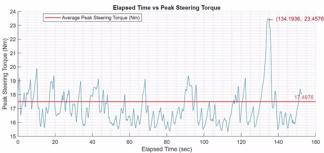
A key part of the project was developing a steering force model that accurately calculates the steering torque needed during a lap.
This was achieved by feeding data from OptimumLap, Susprog3D, StarCCM, and tire data into a MATLAB model which calculated the torque needed dynamically as the lap progressed. An example lapsim result is show in Figure ?.
This allowed me to get a very accurate idea of what forces should be expected on track allowing me to set up accurate FEA load cases to spec the steering system components appropriately.
Designing for Manufacturing
A large part of optimizing the design was keeping the manufacturing method in mind. In most cases, the parts were machined using a lathe or a mill. Therefore, it was crucial that the cutting profiles were simple and achievable for students.
In addition, CAM systems such as water jetting, laser cutting, and 3D printing were used whenever possible to reduce the lead times on parts.